Optical Design
Computational Spectral Imager
Part of my graduate work involved an initial design of a computational spectral imager designed for diagnosing retinal disease.
The basic architecture consists of a transmissive dual disperser design which uses double Amici Prisms and a transmissive spatial light modulator (SLM). In addition, we used commercial off-the-shelf lenses from Edmund Optics to reduce the cost of fabrication.
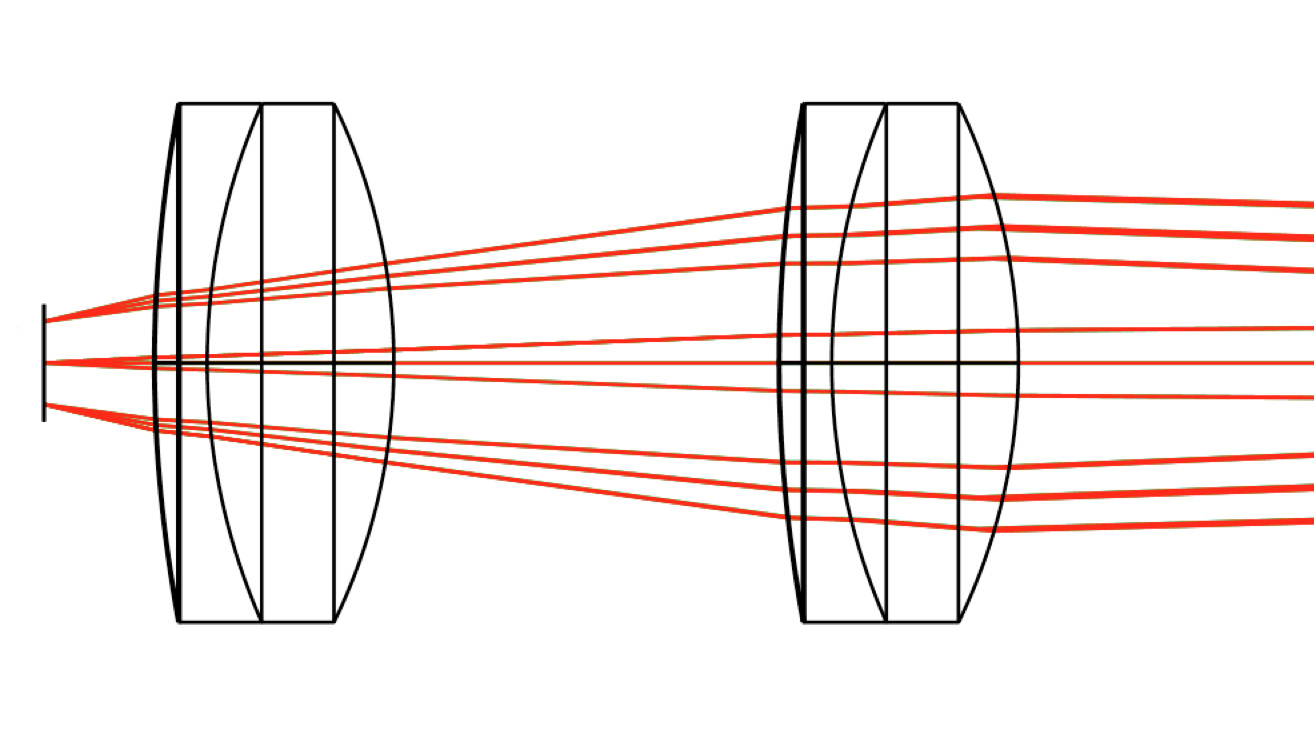
Below is a screenshot of the design:

The first two lens elements are 50mm focal length Aspherized Achromatic Lens from Edmund Optics (Stock No. #49-665). This is shown below:
Double Amici Prism: Once the rays are in collimated space a double Amici prism disperses the light. The double Amici prism has a cool property…it is a non-deviating prism. This means it provides dispersion without deviating the angle of the central wavelength. This reduces the complexity of the instrument. The prism consists of N-SF66 for the two outside materials and N-LAK34 as the inside material.
I attempted to place prism right behind the aperture stop to promote symmetry. By having an optical system that is symmetric about the aperture stop one can significantly reduce coma, distortion, and lateral color.
Coordinate Breaks: Implementing the double Amici prism meant I had the opportunity to learn how to successfully execute coordinate breaks in Zemax. Coordinate breaks are essentially dummy surfaces that do not affect the rays but they affect how surfaces are “constructed” relative to the surface before the coordinate break.
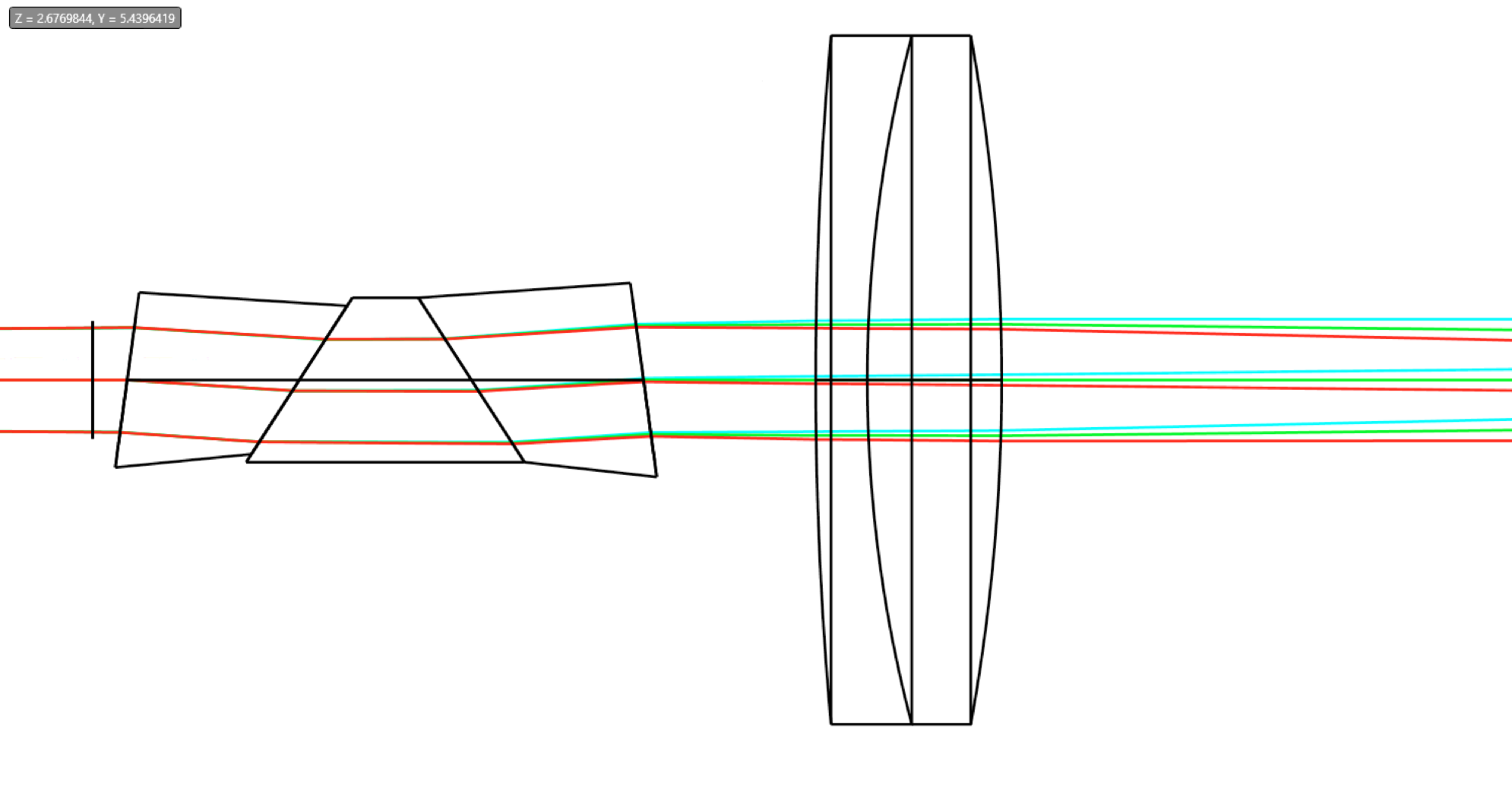
Programmable Spectral Filter: After the prism, a pair of Edmund Optics 180 mm focal length achromatic doublets are used to formed the dispersed image plane. This is where a polarizer and a transmissive spatial light modulator (SLM) and another polarizer is placed. This combination of polarizer, SLM, polarizer can modulate the amplitude of light. By changing the voltage to each pixel one can change how much light is passed. The specific spectral filters are obtained through a calibration step. Below is the dispersed image plane and spot diagram at the dispersed image plane.
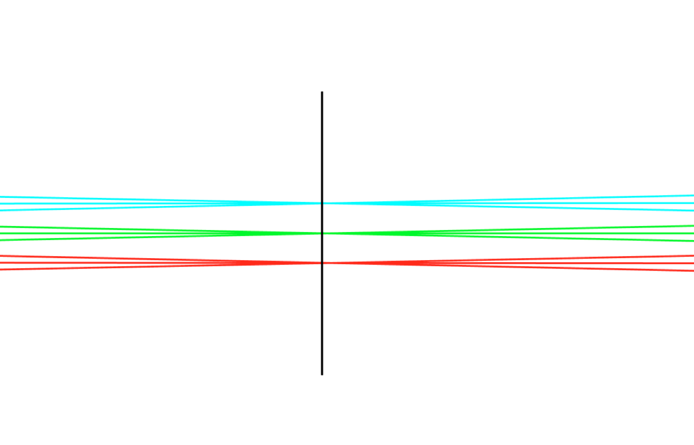
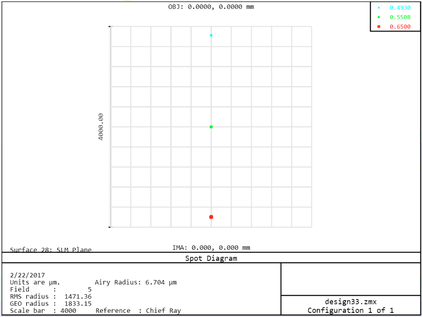
Notice that the central wavelength 550 nm is undeviated from the paraxial chief ray location.
The second half of the system is nearly identical to the first half. Thus this architecture is called a “Dual-Disperser” design. The second half reverses the dispersion created by the first half of the system. Therefore a point in the object plane images to a point in the image plane (with some wavelengths missing due to the spectral filtering), rather than a dispersed line like in a typical spectrometer.
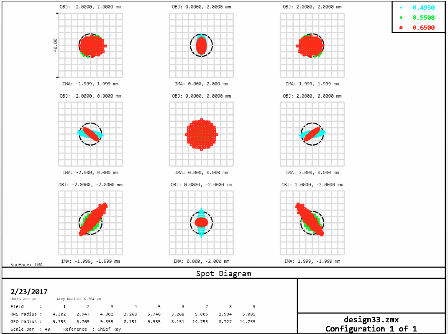
The final image is a well corrected, as seen the spot diagram at the image plane below:
Further improvements: One of the biggest drawbacks of the system is the length. The total track is about 1 meter. By using a reflective liquid crystal on silicon (LCOS) spatial light modulator (SLM) it should be possible to reduce the length by about half.